The devices used for movement control of medical and laboratory equipment (including rotary and linear encoders) have become more compact, reliable, robust and less expensive. Currently, in fact, the technological development of the encoders is one of the most active areas of motion control and this trend seems likely to continue into the future.
In which direction is this development moving?
For a long time manufacturers of medical machines have used incremental optical encoders with digital output as the main positioning control device. Today this type of encoder still dominates the motion control market for sales volume, thanks to its low cost and satisfactory resolution.
In the last ten years, however, new encoder technologies and new data sending methods have been added to it.
Which type of encoder is it better to choose?
To decide which position detection device to use, one must first evaluate the motor types and the mechanisms that must be measured. In principle, position sensors are available in rotary or linear configurations, which reflect the two main types of rotary and linear motor actuators.
Many encoders are based on optical technology. The optical method uses a glass or plastic disk with two sets of windows along the circumference. An LED light source and photodetectors are located on opposite sides of the disk. When the latter turns, the passage or not of light through the windows generates the typical square waves of the pulses of the quadrature outputs A and B.

Incremental rotary optical encoder:
Figure 1 illustrates a basic rotary optical encoder. It transmits position information in square wave format using two wires, called A and B, and provides a “one-per-rotation” pulse index called I or Index. An Index pulse provides a short output signal at each motor rotation. This signal can be used when searching for the reference point or for automatic correction of the loss of count.
Operating often in difficult environmental conditions due to the presence of dust, dirt, temperature variations and vibrations of considerable intensity, the A, B and Index signals of the square-wave encoders are differentially rendered to reduce the possibility of losing counts. But this system is not always infallible, as it is precisely sensitive to external conditions.
In addition to the potential loss of count during the movement, the other implication of an incremental system is that the encoder does not know where it is at the end of the operation. For many systems, this can easily be corrected with a homing sequence executed during startup, but for other applications it is necessary to always know where it is located.
Absolute rotary optical encoder:
This is where the second main category of encoders comes into play, the absolute position encoders, of which the optical sensors are the most common. As the name suggests, these coders always know where they are at the end of the operation.
For rotary engines they are available in single or multi-turn versions, and the output is in binary format or in an alternative format specially adapted for encoders called Gray Coding.
Previously, absolute encoders had thick wire bundles to carry 14, 16, 18 or more bits of location information. Today, increasingly, absolute encoders use serial formats such as BiSS or SSI (Synchronous Serial Interface) to reduce the wire load needed to communicate the position to the controller.
Not only optical encoders:
In addition to incremental and absolute optical encoders, there is an ever-expanding range of innovative techniques to provide higher position resolution and lower cost.
In addition to optical detection techniques, magnetic detection is increasingly popular; followed by capacitive sensing.
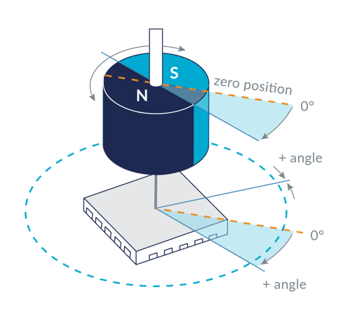
Magnetic encoders use magnetic field sensors instead of a light beam. Instead of the optical disk with the windows, it has a magnetized disk that rotates on a series of magnetoresistive sensors. Each rotation of the disk produces a response from these sensors that arrives at a signal conditioning front-end circuit to determine the position of the shaft.
Previous models tended to have resolutions similar to low-end optical encoders, but with the evolution of technology they are now available with a higher resolution.

The great advantage of the magnetic system is the absence of contact in the detection, a factor that prevents the wear of the device and provides a potentially infinite durability. Magnetic encoders are particularly suitable for applications in harsh environments that require high strength, speed and thermal resistance, while ensuring optimum reliability in signal generation.
While offering a long life, the magnetic encoder is not as accurate as the optical encoder.
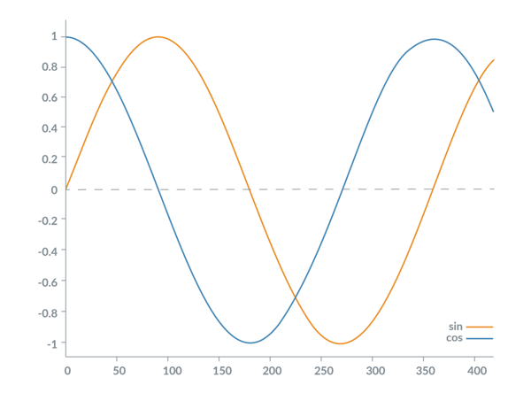
Another rapidly growing encoding technology is the so-called Sin / Cos encoder, whose output waveforms are in the form of a sine / cosine shown in Figure 3. The signals are essentially a sinusoidal variation of the standard wave coding scheme square brackets A and B. These sinusoidal outputs are electronically extrapolated to get more position information. Depending on the quality of the signals, it is possible to obtain an extension of the resolution of 16x up to 1.000x.

The reason why Sin / Cos encoders have become so popular, especially for high-resolution linear applications, is that they allow resolutions of 1 nanometer or higher, and have a low cost. They require only a minimum of additional electronics in the sensor and have a simple intuitive interface composed of four analog signals coded in differential mode (sin +, sin-, cos + and cos-).
Are you wondering how best to control the movement of an automation system for medical and laboratory applications you are designing? Contact us and we will direct you to the most suitable choice for your needs: info@garnetitalia.com
Content inspired by the article “Motion Control Technology Trends for Medical and Laboratory Applications” by Chuck Lewin, on pmdcorp.com